
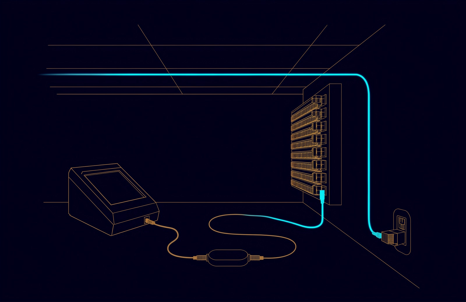
Structured cabling certification proves that every installed link meets the limits of a named standard, and the test report is the evidence. Before you sign the handover, the report should show a PASS for every link, the results behind it (wire map, length, insertion loss, NEXT, return loss), the margins, the tester's calibration date and the native files.
A page of green ticks is not enough: the detail shows the standard, configuration and instrument behind each result, and how close each link came to failing. This article covers the report only; the wider handover pack is in Cat 6A or fibre: what a UAE cabling design actually has to answer for and the cabling itself in our guide to structured cabling and its standards.
What is structured cabling certification?
It is a network cable certification test: a field tester sweeps each link across the frequency range of its category and compares every measurement with the limits in ANSI/TIA-568 or ISO/IEC 11801. How the measurements are made, and how accurate the tester must be, is set by IEC 61935-1:2019 internationally and by ANSI/TIA-1152-A (November 2016) in the TIA family.
IEC 61935-1 names three kinds of field tester, and only one of them certifies. Qualification testers show whether a link will carry an application, but the standard notes that their accuracy is not traceable to national standards.
| Test type | Question it answers | Proves compliance with a cabling standard? |
|---|---|---|
| Verification | Is every wire connected to the right pin at the far end? | No |
| Qualification | Will this link run a given application, such as 1000BASE-T? | No: accuracy not traceable to national standards |
| Certification | Does this link meet the limits of its category in TIA-568 or ISO/IEC 11801? | Yes, if the tester meets the accuracy level for that category |
The tester must also be accurate enough for the frequencies it sweeps. ANSI/TIA-1152-A defines accuracy levels IIe, III, IIIe and 2G (which category each covers). Fluke Networks, a tester manufacturer, notes that IEC 61935-1 uses the same values for IIe, III and IIIe, and the IEC's summary of the 2019 edition says it introduced a level VI field tester for up to 2,000 MHz. A higher level also covers the categories below it.
| Category (ISO/IEC class) | Swept up to (MHz) | Tester accuracy level |
|---|---|---|
| Cat 5e (Class D) | 100 | Level IIe |
| Cat 6 (Class E) | 250 | Level III |
| Cat 6A (Class EA) | 500 | Level IIIe |
| Cat 8 (Class I); Class II is ISO/IEC only | 2,000 | Level 2G (TIA); Level VI (IEC 61935-1:2019) |
Permanent link, channel or MPTL: what was tested?
Every test limit names a configuration as well as a category, and the configurations are not interchangeable. Read the limit name on each record before you read the result.
- Permanent link. The fixed part of the link, typically from the patch panel to the outlet (or a consolidation point), at most 90 m, without the patch and equipment cords. Certify this at handover: as Fluke Networks explains, a passing permanent link plus compliant cords makes a passing channel.
- Channel. The whole path between two active devices, cords included, up to 100 m. Channel limits leave headroom for the cords, so a channel tested with good new cords can pass while the permanent link inside it fails. The plugs that mate with the tester are not measured.
- Modular plug terminated link (MPTL). A horizontal cable ending in a plug that goes straight into a device that rarely moves, such as a camera. It is tested with a permanent link adapter at the panel and a patch cord adapter at the plug, so the field-fitted plug counts. Fluke warns that a channel adapter at that end leaves the plug's connection out of the test and gives optimistic results.
Security cameras are a common MPTL case; for the wider camera picture, see when CCTV becomes a network problem.
The parameters on a copper certification report
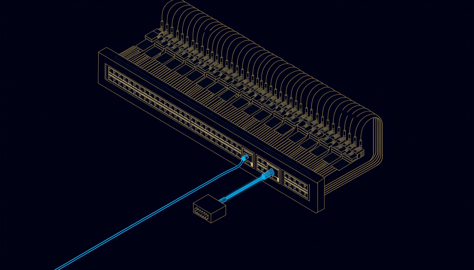
Each record gives an overall PASS or FAIL, then a result for every parameter, with the pair and frequency where it was worst. The core set comes from ANSI/TIA-568.2-E (2024) and ISO/IEC 11801, and IEC 61935-1 defines how each is measured in the field.
| Parameter | What it measures | Unit | A good result |
|---|---|---|---|
| Wire map | Each conductor reaches the right pin: no opens, shorts, reversed, crossed or split pairs | pass or fail | PASS on all eight conductors |
| Length | Electrical length, worked out from signal travel time and the cable's NVP | m | Within 90 (permanent link) or 100 (channel) |
| Insertion loss | Signal lost along the link; rises with frequency, length and temperature | dB | Below the limit at every frequency |
| NEXT and PS NEXT | Crosstalk picked up at the near end from one other pair, and from all three | dB | Above the limit; a higher number means less crosstalk |
| ACR-F and PS ACR-F | Crosstalk at the far end, relative to the signal arriving there | dB | Above the limit |
| Return loss | Signal reflected back by impedance mismatches | dB | Above the limit; higher is better |
| Propagation delay | Time for the signal to travel the link | ns | Within the limit |
| Delay skew | Difference in delay between the fastest and slowest pair | ns | Within the limit |
| DC loop resistance and DC resistance unbalance | Conductor resistance, and how evenly it is shared within and between pairs | Ω | Within the limit; the unbalance test is optional and matters for PoE |
- Wire map catches more than colours. A split pair keeps pin-to-pin continuity, so a continuity tester passes it, but NEXT then fails badly. T568A at one end and T568B at the other shows up as a crossed pair (see our guide to T568A, T568B and patch cord colours).
- Length depends on a setting. The tester derives length from the cable's nominal velocity of propagation (NVP), which should come from the cable maker. According to Fluke, ANSI/TIA-1152 adds a 10 % NVP allowance, so a 90 m permanent link fails on length only past 99 m. Past 90 m, expect insertion loss to fail anyway.
- Insertion loss and return loss point to different faults. In copper, insertion loss grows with length, frequency and temperature; return loss comes from impedance mismatches, kinked cable and too much untwist at a termination.
Other parameters appear only if the limit or the specification asks for them. Balance tests (TCL and ELTCTL) are optional. Alien crosstalk (PS ANEXT and PS AACR-F) shows that Cat 6A will carry 10GBASE-T; Fluke notes that most cabling vendors will not grant a system warranty without it, and that the standards let a specification test it on a sample of links. Agree all of this before testing starts.
Margin, worst-case value and PASS*
Margin is the gap between a measurement and its limit, in dB: positive passes, negative fails. Fluke's guide to its reports defines worst-case margin as the point where the trace came closest to the limit line, which is the one to watch, and worst-case value as the margin where the measurement itself was worst. The two can fall on different pairs. A Cat 6A NEXT plot covers 1 to 500 MHz; the limit falls as frequency rises, and a higher trace is better. The plot below is illustrative and uses a log frequency scale; a tester's own report may draw the axis linearly.
An asterisk marks a result closer to the limit than the accuracy the tester's maker publishes. Fluke reports that TIA and ISO/IEC standards require the mark and still count a PASS* as a pass, and that a tester which lets the asterisk be switched off is not compliant. Unless the specification rejects marginal passes in writing, they stand. They are more likely on links with extra connections, such as a cross-connect or a consolidation point.
| Result on the record | What it means | At handover |
|---|---|---|
| PASS | Every parameter within its limit by more than the tester's accuracy | Accept |
| PASS* | Within the limit, but by less than the tester's accuracy | Accept under TIA and ISO/IEC, unless the contract excludes it in writing |
| FAIL | At least one parameter beyond its limit | Fix and retest; the final record for the link must pass |
Fibre certification: Tier 1 and Tier 2 testing
Fibre is certified with light. Tier 1 uses an optical loss test set (OLTS), a light source at one end and a power meter at the other, to measure total insertion loss, length and polarity against a limit. Tier 2 adds an OTDR trace of each fibre: TIA calls it Tier 2 and ISO calls it extended testing, and an OTDR does not replace the OLTS, because its total loss is inferred rather than measured. Field testing of length, loss and polarity is covered by an annex of ANSI/TIA-568.3-E (2022); the international method is ISO/IEC 14763-3:2024.
| Fibre test | Instrument | What the report shows | Typically required by |
|---|---|---|---|
| Tier 1 (basic) | OLTS: light source and power meter | Total loss (dB) against a limit, length (m), polarity | The standards, and most manufacturer warranties according to Fluke |
| Tier 2 (extended) | OLTS plus OTDR | Also each connector and splice: its loss, reflectance and distance along the fibre | Specifications that ask for it |
On fibre records, check:
- The reference method. Standards recommend the one-jumper reference, which counts the connections at both ends. A two-jumper reference counts one end and can read optimistically; Fluke reports that many cabling vendors reject it.
- The launch condition. Multimode loss testing calls for an encircled flux (EF) compliant source.
- Clean end faces. Fluke names contaminated connections as the most common cause of fibre failures. IEC 61300-3-35 grades end faces, and ISO/IEC 14763-3:2024 made cleanliness inspection normative.
- The OTDR set-up. Launch and tail cords, so the first and last connectors are measured, and traces in both directions averaged, because a one-way reading can misstate a joint's loss.
- The limit used. Building a limit from components, TIA allows up to 0.75 dB per mated connector pair and 0.3 dB per splice. An application can be stricter: 10GBASE-SR allows 2.9 dB of channel loss over 400 m of OM4.
In the UAE, TDRA's buildings telecommunications manual (V3.0, 2024) requires all optical fibre testing in a new building's FTTx network to follow ISO/IEC 14763-3, and the results of copper cable tests (consolidation cabinet to outlet) to be recorded and kept. The developer tests and documents the built infrastructure before the lead operator issues its acceptance certificate.
What to ask for before you sign the handover
- Every link, not a sample. One record per copper link and per fibre, with Cable IDs that match the labels and drawings. A Fluke article on warranties quotes Siemon requiring 100 % certification testing for its 25-year warranty.
- The native files as well as the PDF. The tester's own format (.flw for Fluke LinkWare, or the maker's equivalent) keeps the measurements and set-up; in the same article Siemon says native .flw files have let it find the root cause of marginal or failing links. A PDF is a printout without that data.
- The right test limit on every record: standard, category and configuration, matching the specification, for example a Category 6A permanent link to TIA-568.2 or a Class EA permanent link to ISO/IEC 11801.
- Tester identity and calibration. A Fluke LinkWare report, for example, shows the tester model, the serial numbers of the main and remote units, the software and limits versions and the last calibration date. Fluke recommends annual factory calibration of its copper and fibre modules; check the date was current on test day.
- Cable type and NVP from the cable maker, so the lengths mean something.
- Plot data for every frequency-based test, so a marginal result can be diagnosed later.
- Failures closed: the final record for every link passes, under the agreed PASS* rule.
- Fibre results at Tier 1 for every fibre, reference method recorded, and Tier 2 traces where specified.
- The warranty registration: the manufacturer's certificate, or proof the results were submitted. The 2018 terms of CommScope's 25-year system warranty, for example, required the test results within 60 days of installation and registration within 90 days of completion. CommScope sold its Cable and Connectivity Solutions business to Amphenol in January 2026 (it now operates as CommScope, an Amphenol company), so ask the manufacturer for the terms that apply today.
How UBM handles it
As part of its network and structured cabling work, UBM certifies every link it installs, labels both ends, and hands the test results over with the as-built drawings, port schedules and rack layouts. That work sits in the deployment stage of our six-stage service lifecycle, where commissioning is tested against acceptance criteria written at planning. For cabling, that means agreeing with the consultant before first fix which standard and configuration each link is certified to, how marginal passes are treated, which fibre tier applies and which file formats the handover needs. To have a test report reviewed before you sign it, talk to a UBM engineer.
Questions people ask
What is the difference between cable testing and cable certification?
Testing can mean anything from a continuity check to a full sweep. Certification compares every parameter with the limits of TIA-568 or ISO/IEC 11801, using a tester of the right accuracy level, and cabling manufacturers require it before they grant a system warranty.
Is a PASS* result acceptable?
Under TIA and ISO/IEC standards a PASS* is a pass: the link is within its limit, by less than the tester's accuracy. If you want to reject marginal passes, the specification has to say so in writing before installation.
Should the permanent link or the channel be certified?
The permanent link. It stays in the building, and a passing permanent link plus compliant cords gives a passing channel; a channel test with new cords can hide a weak fixed link.
Is OTDR testing required for fibre certification?
Not by default. Tier 1 testing with a loss test set is the standard requirement and what most manufacturer warranties ask for. Tier 2 adds an OTDR trace when the specification calls for it, on top of the loss test.
How often does a cable certifier need calibrating?
Follow the tester maker's interval. Fluke Networks recommends factory calibration of its measurement modules once a year, and its reports show the last calibration date.
Can old test results be re-certified to a different standard?
Sometimes, if the native files hold all the data needed. Fluke shows fibre loss results taken to ISO/IEC 14763-3 limits being re-evaluated against TIA limits without a retest. A PDF printout does not carry that data.
Sources
- IEC 61935-1:2019, Specification for the testing of balanced and coaxial information technology cabling, Part 1: Installed balanced cabling (IEC, 2019), with its published preview of the scope and contents
- TIA issues New Requirements for Field Test Instruments and Measurements for Balanced Twisted-Pair Cabling Standard (ANSI/TIA-1152-A) (TIA, 2016)
- TIA Publishes New Standards: ANSI/TIA-568.2-E and ANSI/TIA-568.5-1 (TIA, 2024)
- ANSI/TIA-568.3-E, Optical Fiber Cabling and Components Standard: summary (TIA Fiber Optics Technology Consortium, 2022)
- ISO/IEC 14763-3:2024, Implementation and operation of customer premises cabling, Part 3: Testing of optical fibre cabling (ISO/IEC, 2024), with its published preview of the foreword and scope
- Buildings Telecommunications Network Specification Manual: Guidelines for FTTx in new Buildings, V3.0 (TDRA, 2024)
- CommScope Network Infrastructure System 25 Year Extended Product and Application Warranty: Terms and Conditions (CommScope, 2018)
- Amphenol Completes Acquisition of CommScope's Cable and Connectivity Solutions Business (Cabling Installation and Maintenance, January 2026)
- Testing the testers that will test Category 8 (Cabling Installation and Maintenance, January 2014)
- ANSI/TIA-1152-A: Requirements for Field Test Instruments for Twisted-Pair Cabling (Fluke Networks knowledge base, first published 2014)
- Channel, Permanent Link, Patch Cords, MPTL, E2E… Oh My! (Fluke Networks, 2019)
- Top 10 Cable Testing Mistakes (Fluke Networks, 2025)
- Cabling Mistakes #2 and #3: Neglecting Marginal Test Results and Parameters (Fluke Networks, 2016)
- Cable Testing 101: How to Read the LinkWare PC Report (Fluke Networks, 2016)
- Cable Testing 101: Understanding Your LinkWare Report (Fluke Networks, 2016)
- Wire Map Testing: It's Not All About Color (Fluke Networks, 2018)
- Length measurements for the DSX CableAnalyzer Series Testers (Fluke Networks, 2015)
- Insertion Loss vs Return Loss: Performance Parameters (Fluke Networks, 2024)
- OLTS and OTDR: A Complete Testing Strategy (Fluke Networks, undated, read October 2026)
- Cable Testing 101: What's My Loss Budget? (Fluke Networks, 2019)
- Know How to Determine Your Versiv Module Calibration Due Date (Fluke Networks, 2019)
- ROI of Certification Testing: Warranty and Certification Go Hand in Hand (Fluke Networks, 2024)
- Re-Certified Test Reports, Part 2: Fiber Optic Tests (Fluke Networks, 2020)

Comments
Questions and experience from readers. A person reads every comment before it appears.
No comments yet. If something here does not match what you have seen on site, say so.