
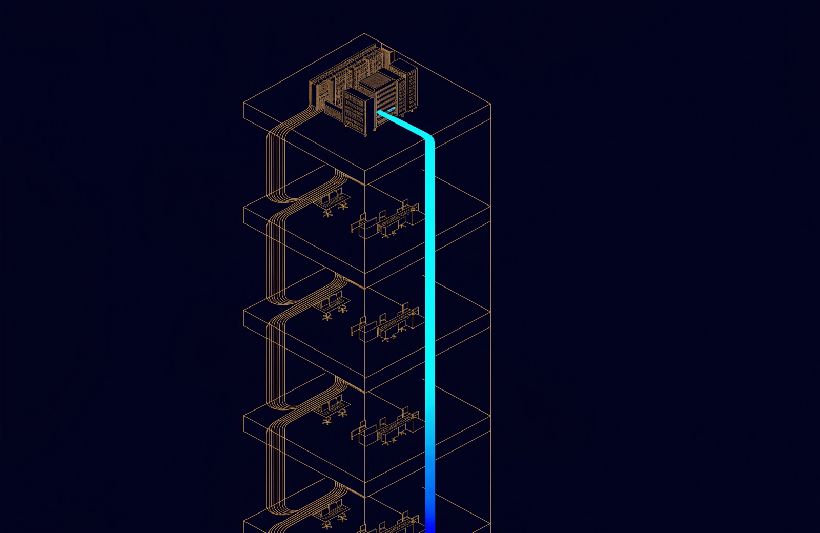
Every structured cabling tender we are asked to price contains the same sentence: Cat 6A U/UTP throughout, 25-year warranty. It is not a specification. It is a purchase order with a standard number attached, and it leaves four questions unanswered, each of which shows up as a change order eighteen months later.
The 90 metres is not negotiable, and it is not 90 metres
ANSI/TIA-568.2-D and ISO/IEC 11801-1 both fix the horizontal permanent link at 90 m of solid-core cable, with a 10 m allowance for patch cords at both ends. The number people forget is that the 10 m is a total, not a per-end figure. A 4 m patch cord in the rack and a 5 m cord at the desk leaves you 1 m of margin on a link that was already routed the long way round a fire compartment.
On a floor plate wider than about 55 m from the riser, the honest answer is a second telecommunications room, not a longer run. We have twice been asked to certify links at 96 m because a consultant measured on the drawing rather than along the tray. Both failed. Both were rebuilt.
What to fix at design stage
- Measure along the cable route, including the vertical drop and the service loop, not across the floor plan.
- Budget a 3 m service loop above the ceiling at the outlet end. It is what makes a partition move a two-hour job instead of a re-pull.
- Place the TR so the furthest outlet is under 80 m of routed cable. The last 10 m is your margin for the churn you cannot predict.
Alien crosstalk is the reason Cat 6A is not just Cat 6 with a bigger number
Cat 6A is qualified to 500 MHz, and above roughly 250 MHz the dominant noise is no longer pair-to-pair inside a cable. It is pair-to-pair between adjacent cables. That is alien crosstalk (ANEXT), and it is the parameter a U/UTP installation fails on when 48 cables are bundled tight in a 300 mm tray for a 40 m run.
The mitigations are all physical, and all cheaper to design in than to fix:
- F/UTP (foil over the four pairs) removes ANEXT as a practical concern and shortens the sheath diameter compared with the fat U/UTP constructions built to separate the pairs mechanically. It requires a bonded pathway back to the TR earth bar, which is a discipline, not a difficulty.
- Loose bundling. Cable ties pulled to a neat 25 mm bundle are the single most common cause of a failed ANEXT margin. Hook-and-loop, laid not cinched.
- Separation at the patch panel. Most of the coupling happens in the last 2 m, where every cable in the bundle terminates side by side.
PoE changed the thermal calculation, and the UAE changed it again
IEEE 802.3bt Type 4 delivers up to 90 W at the PSE, and a meaningful part of that is dissipated as heat inside the bundle. TIA TSB-184-A gives the derating: a 100-cable bundle carrying Type 4 power can run 10 °C above ambient at the centre, and insertion loss rises roughly 0.4 % per degree.
Ambient in an air-conditioned floor plate is 24 °C. Ambient in an uncooled riser in Abu Dhabi in August, with the shaft acting as a chimney, is not. We have logged 44 °C in a riser at 15:00 in a building that was signed off as compliant. The channel that passed at commissioning in February had no margin left in August.
| Bundle | Ambient | Centre rise | Usable length |
|---|---|---|---|
| 24 cables, Type 3 | 24 °C | ~4 °C | 90 m |
| 48 cables, Type 4 | 24 °C | ~8 °C | 88 m |
| 48 cables, Type 4 | 45 °C | ~8 °C | 72 m |
| 96 cables, Type 4 | 45 °C | ~12 °C | 66 m |
Two practical consequences. First, size riser bundles at 24 cables and accept more of them rather than fewer, larger ones. Second, if the riser is uncooled, design the horizontal to 75 m, not 90 m, and say so in the drawing notes so the next contractor does not spend your margin.
Where fibre stops being an upgrade and starts being cheaper
Fibre to the desk is still the wrong answer for a general office floor: the media converters and the powered outlets cost more than the copper they replace. The calculation flips in three specific places.
1. Backbone, always
OM4 for anything inside a building under 150 m, OS2 single-mode between buildings and for any run that might one day carry 40G or 100G. The cost delta between OM4 and OS2 in a duct is the cable, not the labour, and the labour is 80 % of the bill.
2. Runs that break the 90 m rule for structural reasons
A single-mode pair to a remote fibre-to-the-edge switch beats a second telecommunications room in a building where there is no room to put one: a heritage envelope, a hotel back-of-house, a plant room.
3. Environments where the copper will not survive
External CCTV routes, plant rooms, kitchens, car parks and anywhere the pathway crosses an expansion joint. Fibre has no electrical bonding requirement and does not carry a fault between buildings.
The handover pack is the deliverable
The 25-year warranty in the tender is issued by the manufacturer, not by the installer, and every manufacturer conditions it on evidence. A pack that will actually be accepted contains:
- Permanent link test results for 100 % of outlets, from a Level IIIe (Cat 6A) field tester inside its calibration period, exported in the tester's native format, not a PDF summary. The native file is what the manufacturer's warranty desk re-reads.
- OTDR traces plus insertion loss in both directions for every fibre strand, with the launch and tail cord lengths recorded.
- Labelling to ANSI/TIA-606-C, and the same identifiers on the drawing, the panel, the outlet and the test file. Three matching and one different is the normal failure.
- As-built drawings showing actual routes, not design intent, with the TR earth bar and the bonding conductor sizes shown.
- A rack elevation per TR, with the U position of every panel and switch, and the spare capacity stated as a number.
None of this is exotic. All of it is the difference between a building whose passive layer can be handed to the next contractor and one where the first task of every future project is a survey.
Comments
Questions and experience from readers. A person reads every comment before it appears.
No comments yet. If something here does not match what you have seen on site, say so.